Control & Measurement
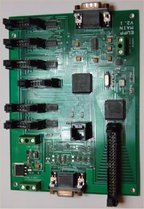
 EUPP Modules - Main board
The main board has the following features;
*
PIC 16F877 micro controller clocked at 20 MHz.
*
8K non volatile Flash program memory.
*
368 bytes of RAM.
*
256 bytes of EEPROM data memory, with program read / write
access.
*
Power supply which accepts DC voltages in the range (7V to
30V), provides a +5V DC supply to control all on board logic. An
output connection is provided in case external equipment
requires a +5V DC supply. The on board logic supply uses an
enlarged copper area to provide heat sinking for current draw of
around 100 mA, although the regulator chip is capable of
providing current up to 1A. For currents in excess of 200 mA, the
regulator chip is not fitted to the PCB, but is fitted externally and
an external heat sink is fitted. As well as current draw from the
on board +5V supply, the difference between +5V and the plant
supply will determine if an external heat sink is required.
*
Analogue inputs, which are accessed via a 9 way D-type socket.
Note analogue input range and whether any inputs are allocated
as voltage references are fixed at time of manufacture and can
not be changed later.
*
RS232 port with hardware handshaking which is accessed via a
9 way D-type plug.
*
34 element LED display, note the actuarial display must be
ordered separately but connects directly to a 40 way connector
on the main board.
*
Pulse wave modulated output, which is accessed via a two way
screw connector on the main board.
*
Three digital input ports, one 6 bit high speed port and two 8 bit
standard speed ports. All ports can only be used after fitting a
digital input board.
*
Three digital output ports, all ports are 8 bits wide, but can only
be used after fitting the appropriate digital output board
(standard or isolated) or LCD display board.
EUPP Modules - Main board
The main board has the following features;
*
PIC 16F877 micro controller clocked at 20 MHz.
*
8K non volatile Flash program memory.
*
368 bytes of RAM.
*
256 bytes of EEPROM data memory, with program read / write
access.
*
Power supply which accepts DC voltages in the range (7V to
30V), provides a +5V DC supply to control all on board logic. An
output connection is provided in case external equipment
requires a +5V DC supply. The on board logic supply uses an
enlarged copper area to provide heat sinking for current draw of
around 100 mA, although the regulator chip is capable of
providing current up to 1A. For currents in excess of 200 mA, the
regulator chip is not fitted to the PCB, but is fitted externally and
an external heat sink is fitted. As well as current draw from the
on board +5V supply, the difference between +5V and the plant
supply will determine if an external heat sink is required.
*
Analogue inputs, which are accessed via a 9 way D-type socket.
Note analogue input range and whether any inputs are allocated
as voltage references are fixed at time of manufacture and can
not be changed later.
*
RS232 port with hardware handshaking which is accessed via a
9 way D-type plug.
*
34 element LED display, note the actuarial display must be
ordered separately but connects directly to a 40 way connector
on the main board.
*
Pulse wave modulated output, which is accessed via a two way
screw connector on the main board.
*
Three digital input ports, one 6 bit high speed port and two 8 bit
standard speed ports. All ports can only be used after fitting a
digital input board.
*
Three digital output ports, all ports are 8 bits wide, but can only
be used after fitting the appropriate digital output board
(standard or isolated) or LCD display board.