Control & Measurement
 EUPP Demonstration Units - Lamp demo unit
This systems demonstrates;
* Processing multiple analogue inputs
* Pulse wave modulated (PWM) signal control
* Use of LED display
* Using LED display to convey additional data
* Use of remote control from a PC
The system takes the signal from one of the analogue inputs, the value of this signal will be displayed on the LED
display. Additional data is conveyed on the LED display as the four decimal places are used to indicate which
analogue signal is currently being processed. The Red and Green LED's indicate the direction the PWM signal is
varied in relation to the analogue input. A computer connected to the system by a serial cable, allows the active
analogue source to be selected as well as the direction of variation of the PWM signal.
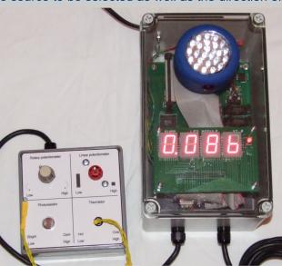
EUPP Demonstration Units - Lamp demo unit
This systems demonstrates;
* Processing multiple analogue inputs
* Pulse wave modulated (PWM) signal control
* Use of LED display
* Using LED display to convey additional data
* Use of remote control from a PC
The system takes the signal from one of the analogue inputs, the value of this signal will be displayed on the LED
display. Additional data is conveyed on the LED display as the four decimal places are used to indicate which
analogue signal is currently being processed. The Red and Green LED's indicate the direction the PWM signal is
varied in relation to the analogue input. A computer connected to the system by a serial cable, allows the active
analogue source to be selected as well as the direction of variation of the PWM signal.


 Move the mouse over the pictures
above and I will explain what you
are looking at.
Move the mouse over the pictures
above and I will explain what you
are looking at.

The four analogue transducers that
the system can access are located
here.
This is the lamp whose brightness
is controlled by the selected analogue
source.
The LED display shows the value
of the selected analogue source, and
the red and green LED’s indicate the
direction of lamp brightness change
versus analogue value.
This section of the software
window allows the analogue
source to be selected.
This section of the software
allows you to set the direction of
lamp brightness change compared
to analogue source value.
This section of the software allows
the selected parameters to be sent
to the demo unit and the state of
the comms link to the checked.