Control & Measurement
 EUPP Demonstration Units - Stepper motor demo unit
 This systems demonstrates;
* Stepper motor control
* Monitoring and acting on multiple switches
* Controlling multiple indicators
* Monitoring multiple proximity sensors
* Use of LED display
* Use of remote control from a PC
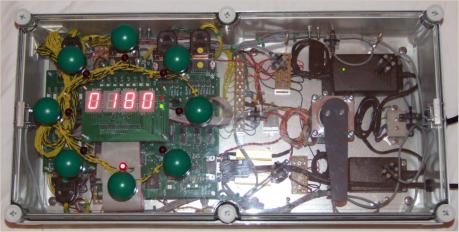
The system monitors 8 switches and when a switch is pressed the system controls the stepper motor and moves
the pointer to the appropriate angle. Once the pointer had been positioned its location is verified by checking
eight proximity sensors, once the pointer position is confirmed the appropriate indicator is set and the pointer
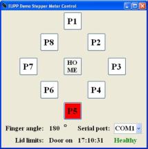
angle is displayed on the LED display. Control is duplicated on a computer linked to the system by a serial cable,
the PC program is also updated with system status such as pointer angle and limit switch status.
This systems demonstrates;
* Stepper motor control
* Monitoring and acting on multiple switches
* Controlling multiple indicators
* Monitoring multiple proximity sensors
* Use of LED display
* Use of remote control from a PC
The system monitors 8 switches and when a switch is pressed the system controls the stepper motor and moves
the pointer to the appropriate angle. Once the pointer had been positioned its location is verified by checking
eight proximity sensors, once the pointer position is confirmed the appropriate indicator is set and the pointer
angle is displayed on the LED display. Control is duplicated on a computer linked to the system by a serial cable,
the PC program is also updated with system status such as pointer angle and limit switch status.


 Move the mouse over the pictures
above and I will explain what you
are looking at.
Move the mouse over the pictures
above and I will explain what you
are looking at.